LINARIX Linear Sensor
LD0-E2A2B-1216-3D00-PRM
POSITAL
Measuring Tools & Sensors
IP64 / IP65, Draw Wire - 3 m – 6.9 m (9.84' – 22.63'), Powerlink, 16 bit (65536 Steps), Draw Wire Enclosure - Machined Metal - Rectangular Housing, Connector - Radial 3 x M12, Radial 0 / Axial, Optical (≤ 0.02°)
Available
0
General Data Supply Voltage 10 – 30 VDC Power Consumption ≤ 2.5 W Turn On Time < 1 s Operating Temperature -40 °C (-40 °F) - +80 °C (+176 °F) Weight 705 g (1.55 lb) Protection Class (Encoder) IP64 / IP65 EMC: Emitted Interference DIN EN 61000-6-4 EMC: Noise Immunity DIN EN 61000-6-2
Mechanical Data Max. Measurement Length 3.00 m (9.84') Length per Revolution 200 mm Wire Material Plastic Coated Stainless Steel Wire Diameter 0.61 mm Encoder Housing Material Steel Draw Wire Housing Material Zinc Die-cast Max. Speed of Wire Displacement 0.8 m / s Max. Wire Acceleration 1.0 g Max. Extension Force 3.0 N Min. Retraction Force 2.5 N Actuation Lifetime Not Available Wire Mounting M6 Thread Max. Wire Exit Angle ±0°
Sensor Data Technology Optical (≤ 0.02°) Accuracy ±0.012 % FSO Repeatability ±0.005 % FSO Resolution [Encoder - Singleturn] 16 bit Resolution [Encoder - Multiturn] 12 bit Approx. Linear Resolution 3.1 µm (theoretical), limited by mechanics Output Code Binary
Interface Communication Interface Ethernet POWERLINK V2 Profile Powerlink V2, DS-406 Programming Functions Resolution, time base and filter for velocity, preset, counting direction, IP-Address Manual Functions IP-Adress switch 0-255 Transmission Rate 10 / 100 Mbit Cycle Time Interface ≥ 400 µs
Outputs Output Driver Ethernet Current Consumption ≤ 230 mA @ 10 V DC, ≤ 100 mA @ 24 V DC Reverse Polarity Protection Yes Short Circuit Protection Yes Electrical Lifetime >10⁵ h
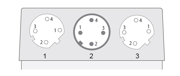
Electrical Connection Connection Orientation Radial Connection Orientation (w.r.t Draw Wire) Radial 0 / Axial Connector 1 M12, Female, 4 pin, d coded Connector 2 M12, Male, 4 pin, a coded Connector 3 M12, Female, 4 pin, d coded
Product Life Cycle Product Life Cycle Established
Connection Plan SIGNAL CONNECTOR PIN NUMBER Tx+ Connector 1 1 Rx+ Connector 1 2 Tx- Connector 1 3 Rx- Connector 1 4 Power Supply Connector 2 1 Not Connected Connector 2 2 GND Connector 2 3 Not Connected Connector 2 4 Tx+ Connector 3 1 Rx+ Connector 3 2 Tx- Connector 3 3 Rx- Connector 3 4
Connector-View on Encoder
All dimension in [inch] mm. Encoder dimensions may vary depending on electrical interface and connector. This drawing and the information contained is for general presentation purposes only. Please refer to the "Download" section for detailed technical drawings.
© FRABA B.V., All rights reserved. We do not assume responsibility for technical inaccuracies or omissions. Specifications are subject to change without notice.